Case Study — Induction Coating Removal — Permian Basin, West Texas
In the Permian Basin, a major petroleum storage operator needed epoxy liner stripped from the critical zone of a crude oil storage tank — fast, clean, and with minimal disruption. Using a dual-machine induction setup, we completed the full scope two days ahead of schedule with zero secondary waste and no return passes required.
Project Snapshot
Location: Permian Basin, West Texas
Asset: Crude oil aboveground storage tank
Coating: Epoxy liner — floor and lower shell wall
Scope: Critical zone: 18″ inboard on floor + 18″ up shell wall + full perimeter weld seam
Equipment: RPR-1650 Induction Disbonder (floor) + RPR-1032 Compact Disbonder (walls & corner weld)
Power: 185 kVA, 480V, 3-phase generator
Cooling: Cold-Shot chiller — recirculated and chilled cooling water for the RPR-1650
Crew: 4 Technicians
Conditions: Post-seal removal; residual crude oil contamination on interior surfaces
Schedule: Completed 2 days ahead of schedule
The Challenge
Epoxy liners applied to crude oil storage tanks are designed to be thick, chemically resistant, and tenacious — qualities that make them extremely difficult to remove when a tank requires inspection, recertification, or recoating. Full removal of the existing liner is required before any new coating system can be applied, and the liner’s adhesion and thickness make this one of the most demanding surface preparation tasks in industrial maintenance.
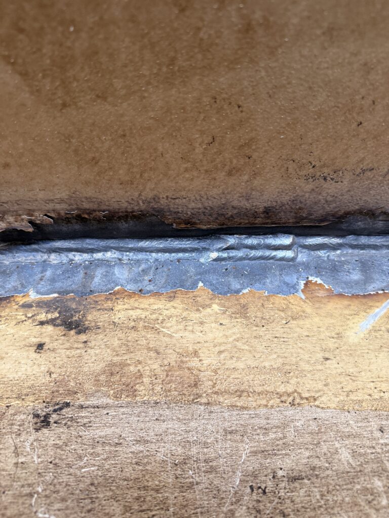
The most critical area of any tank is the perimeter weld — where the floor plate meets the shell wall. This annular zone sees concentrated stress, product settlement, and moisture ingress, making it the most likely area for coating failure and corrosion initiation. It is also the hardest zone to strip cleanly. The defined critical zone on this project included 18″ inboard on the floor, 18″ up the shell wall, and the full perimeter weld seam running the tank’s circumference.
Conventional approaches carry real drawbacks in this kind of scope:
- Abrasive blasting — generates large volumes of grit and dust requiring cleanup, and is slow and difficult to work cleanly in corner geometry.
- UHP water jetting — effective on flat surfaces but introduces water into the tank, adding pump-out requirements and complications to the project schedule.
- Manual chipping and needle-gun scaling — extremely slow and poorly suited to corner weld geometry.
An additional complication on this project: the tank had recently had its seal removed and had not been fully cleaned, leaving residual crude oil contamination on interior surfaces. Coldsweep was engaged to strip the epoxy liner across the full critical zone using induction technology.
Technical Approach
How Induction Coating Removal Works
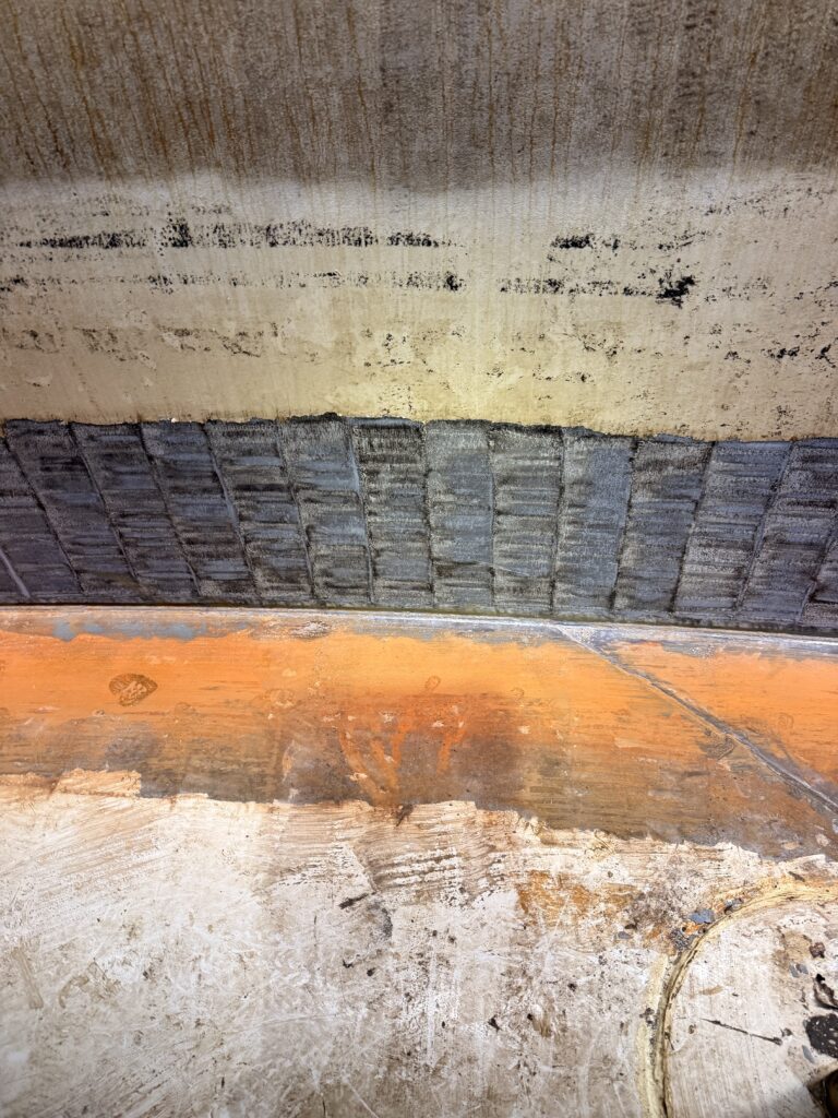
Both RPR units deployed on this project operate on the same electromagnetic induction principle. A targeted magnetic field is generated at the induction head and induces eddy currents in the steel substrate. The natural resistance of the steel converts those currents into heat — approximately 300°F at the bond line, directly between the steel and the coating. This rapid, localized heating causes thermal disbondment of the coating from the substrate without abrasive contact, chemicals, or open flame. The coating releases in strips and sheets, leaving a clean steel surface.
Equipment Deployed
- RPR-1650 Induction Disbonder — high-output unit used for large flat floor passes
- RPR-1032 Compact Induction Disbonder — deployed on the shell walls and corner weld seam for precise, controlled heat delivery in tighter geometry
- Flat induction heads (multiple sizes) — used on both floor and wall passes
- 90° Corner Induction Head — used on the RPR-1032 for continuous disbondment through the full corner radius
- 185 kVA, 480V, 3-phase generator — primary power for both induction units
- Cold-Shot chiller — recirculated and chilled the RPR-1650 cooling water to maintain stable operating temperatures during extended runs
- Wire wheel grinder — used at the corner weld immediately after each induction pass while the steel was still hot
- Scrapers — used on the floor and wall to clear loosened liner material as each pass was completed
Three-Zone Process Sequence
Zone 1 — Tank Floor (18″ inboard) — RPR-1650 with flat inductors: The 1650’s higher power output was well matched to driving heat through the large flat floor plate. Flat induction heads were worked in overlapping passes following the RPR work-pattern protocol — heating every second field and returning on cooled sections to avoid overheating the steel. Loosened liner material was cleared with scrapers as each section was completed.
Zone 2 — Shell Wall (18″ up from weld) — RPR-1032 with flat inductors: The 1032’s compact form factor and precise power delivery made it the right tool for the vertical shell surface. Flat induction heads were worked in horizontal passes up the wall, with the operator managing head contact against gravity on the softening liner. Disbonded material was cleared with scrapers as work progressed.
Zone 3 — Perimeter Weld Seam — RPR-1032 with 90° Corner Head: The 90° corner head was powered by the 1032 and applied directly to the weld seam, simultaneously heating the floor plate and shell plate through the full corner radius. This allowed continuous disbondment along the entire seam without repositioning or bridging gaps. A wire wheel grinder was used immediately after each pass while the steel remained hot at approximately 300°F, clearing residual fragments in a single action and eliminating any return visit to the corner.
Mobilization
From arrival on site, the crew had both induction units set up, the generator and chiller connected, and were operational inside the tank within approximately 4 hours. Induction’s minimal infrastructure requirements — no blast pot, no media delivery system, no abrasive stockpile — directly enable this kind of fast mobilization in a tank environment.
Results
- Completed 2 days ahead of schedule, directly reducing the operator’s tank downtime and return-to-service costs.
- Full mobilization and in-tank operations within approximately 4 hours of arrival — no blast pot setup, no media delivery infrastructure, no extended rigging.
- Complete epoxy liner removal across the full critical zone — floor, wall, and perimeter weld — in a single mobilization.
- RPR-1032 with 90° corner head cleared the entire perimeter weld seam in a single continuous pass — no bridging, no repositioning, no missed areas.
- Wire wheel hot-follow at the corner eliminated any return visit to the most difficult section of the critical zone.
- Zero secondary waste: coating came off in strips and sheets, collected and disposed per the project waste plan — no grit, no blast media, no contaminated water.
- Effective performance in a crude-contaminated, post-seal-removal environment with no disruption to adjacent operations.
- Substrate integrity maintained — no anchor profile reduction, no abrasive media embedment.
Induction vs. Conventional Methods
Waste handling: Induction coating comes off in strips and sheets that are easy to collect and bag. Abrasive blasting leaves grit and dust requiring sweeping and vacuuming. UHP water jetting produces contaminated water that has to be pumped out.
Noise: Induction operates near-silently. Abrasive blasting regularly exceeds 95 dB. UHP jetting is loud from both the pump and the lance.
Substrate damage risk: Because induction involves no abrasive contact, there is no risk of anchor profile reduction or media embedment. Abrasive blasting carries the risk of reducing or altering the substrate profile. Water jetting introduces no abrasive media.
Speed on thick coatings: Induction disbonds thick epoxy liners in large sheets, making it fast on heavy builds. Abrasive blasting abrades incrementally and is slow on thick coatings. UHP jetting is moderate.
Water introduction: Induction introduces no water. Abrasive blasting introduces no water. UHP jetting introduces water into the tank, adding a pump-out step to the project.
Concurrent operations: Because induction is silent and produces no airborne media, other crews can work nearby simultaneously. Abrasive blasting and water jetting create hazardous conditions for anyone in the area.
Conclusion
This Permian Basin project demonstrated how a properly matched induction setup outperforms conventional methods across every dimension of a tank critical-zone project. By pairing the RPR-1650 for high-output floor stripping with the RPR-1032’s precision on the walls and corner weld — supported by a 185 kVA generator and Cold-Shot chiller — we completed the full scope two days ahead of schedule with zero secondary waste and no return passes required.
The RPR-1032 with 90° corner head proved decisive at the perimeter weld. The corner seam — historically the most labor-intensive and least cleanly stripped section of any tank floor — was cleared in a single continuous pass. Combined with fast mobilization and a hot-follow wire wheel technique at the corner, induction delivered a schedule and quality outcome that conventional methods could not match in this environment.
If you’re planning a tank inspection, recoat, or maintenance project involving coating removal, we’d be glad to talk through the scope.